TCH.1C-27J-2-27JG
3.By means of external power feeder, supply 5 Vdc
between the pins 32 (+) and 35 (-) of the connector
(2TFA), then connect the DVM between the pins 34
(signal ref) and 33 (-) of the same connector.
4.Using the flap control lever (1), move the flaps at
position shown in the following table and check that
the voltage reading is as per the related collumn.
5.Remove the external power supply and DVM, then
reconnect the aircraft connector (2TAF) to the BIU
NO. 2.
6.Disconnect the aircraft connector (1TFA) from the BIU
NO. 1 (avionic rack (302 VE) ).
7.By means of external power feeder, supply 5V d.c.
between the pins 32(+) and 35(-) of the
connector(1TAF), then connect the DVM between the
pins 34 (signal ref) and 33 (-) of the same connector.
8.Using the flap control lever (1), move the flaps at
position shown in the following table and check that
the voltage reading is as per the related collumn.
9.Remove the external power supply and DVM, then
reconnect the aircraft connector (1TAF) to the BIU
NO. 1.
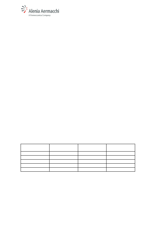
Flap lever position
Flap angle surfaces
Voltage reading (V)
Voltage radio
trasducer LH–RH
UP
0° -1mm / +7mm
0.33 ± 0.1
6.76 %
1
11.25°
1.35 ± 0.1
27.04 %
2
22.5°
2.3 ± 0.1
46.02 %
3
33.75°
3.3 ± 0.1
66.02 %
Full
45°
4.22 ± 0.1
84.40 %
FOLLOW ON MAINTENANCE:
None
27-50-70
2-635